Crownstone installation

General instructions for the installation can be found in the Installation page. The instructions below will take you step-by-step through the process of installing a Crownstone behind a double socket.

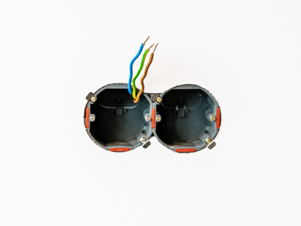
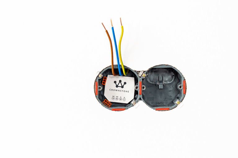
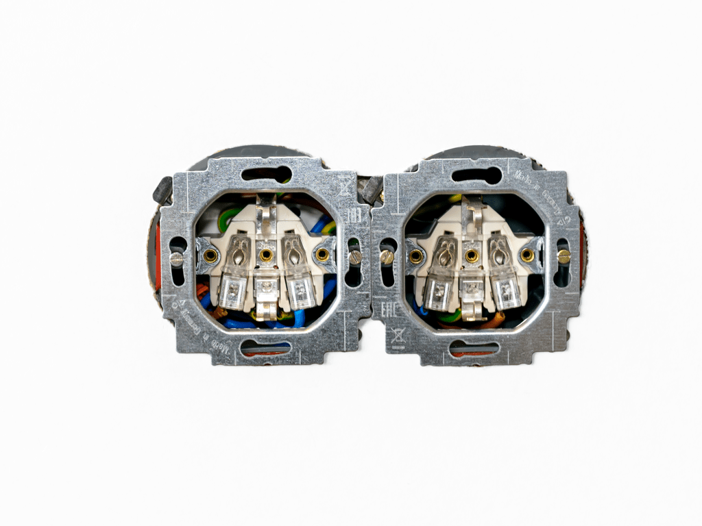
The Crownstone switches both sockets at the same time. To be able to switch the sockets separately, a Crownstone will have to be placed behind each individual socket and it is not possible to loop through as described. For the wiring, the manual for a single socket must then be followed twice.

Step 0

Step 1: Before installing your built-in Crownstones, turn off the power at the fuse box.

Step 1

Step 2: Remove the cover from the socket. This can be done by loosening the screw in the middle of the socket.

Step 2

Step 3: Unplug the metal frame from the power outlet. This can be done by loosening the screws on the left and right.

Step 3

Step 4: Disconnect the wires. Keep them, at least the yellow-green one that has been looped from one outlet to another.

Step 4

Step 5: Remove the metal frame from the other outlet. This can be done again by loosening the screws on the left and right. Disconnect the wires again.

Step 5

Step 6: Take two welding caps with 3 inputs each.

Step 6

Step 7: This is how the welding caps and the Crownstone will be placed. Bend in advance the incoming wires along the top.

Step 7

Step 8: Cut two short blue and two short brown threads at about 10-15 cm. Cut one long blue and one long brown thread at about 20-25 cm.

Step 8

Step 9: Strip all wires at about 9mm on each side.

Step 9

Step 10: Plug a short brown wire into “out/phase”. Plug a short blue wire into “out/N” of neutral.

Step 10

Step 11: Insert a new short brown wire “in/line”. Insert a new short blue wire into “in/N”. Insert the other ends of these wires into the two splice caps, one wire per splice cap. This is because one of the splice caps is for looping through the blue (phase) wires and the other is for looping through the brown (neutral) wires.

Step 11

Step 12: A side view showing how to connect the wires.

Step 12

Step 13: Push the Crownstone and the welding caps into the back box.

Step 13

Step 14: From the wires coming out of the wall, insert the brown (phase) wire into the splice cap with the other brown wire. Plug the other blue (neutral) wire into the weld cap with the blue wire. Color by color.

Step 14

Step 15: You can now also insert the long wires into the welding caps (again color by color). Plug them into the intermediate connection between the flush-mounted boxes.

Step 15

Step 16: Plug the short brown and blue wires back into the socket. Also plug in the yellow-green ground wire. Insert another yellow-green wire into the loop-through hole. If this was not available when dismantling, it is important to also cut it.

Step 16

Step 17: Push the Crownstone back together with the wiring and push the metal frame close to the junction box. Tight the screws on both sides well.

Step 17

Step 18: Attach the wiring to the second outlet. Make sure the phase, neutral, and ground are in the correct inputs.

Step 18

Step 19: Also press the metal frame close to the flush-mounted box and screw the screws on both sides well again.

Step 19

Step 20: Put the cover of the socket back.

Step 20

Step 21: Put the power back on the socket and, of course, test whether the Crownstone is properly connected. The relay in the Crownstone does not necessarily have to conduct when it comes from the factory. Testing is therefore best done by configuring the Crownstone in the smartphone app.