Current
Here we show 50 subsequent buffers with current measurements. Each buffer contains a 100 samples. The more red the curve the newer the curve. There is a slight drift to the left. This means that the next cycle is sampled slightly faster than within 20 msec. Note, that between measurements there might be a period in which we do not sample (we might skip one or more periods).
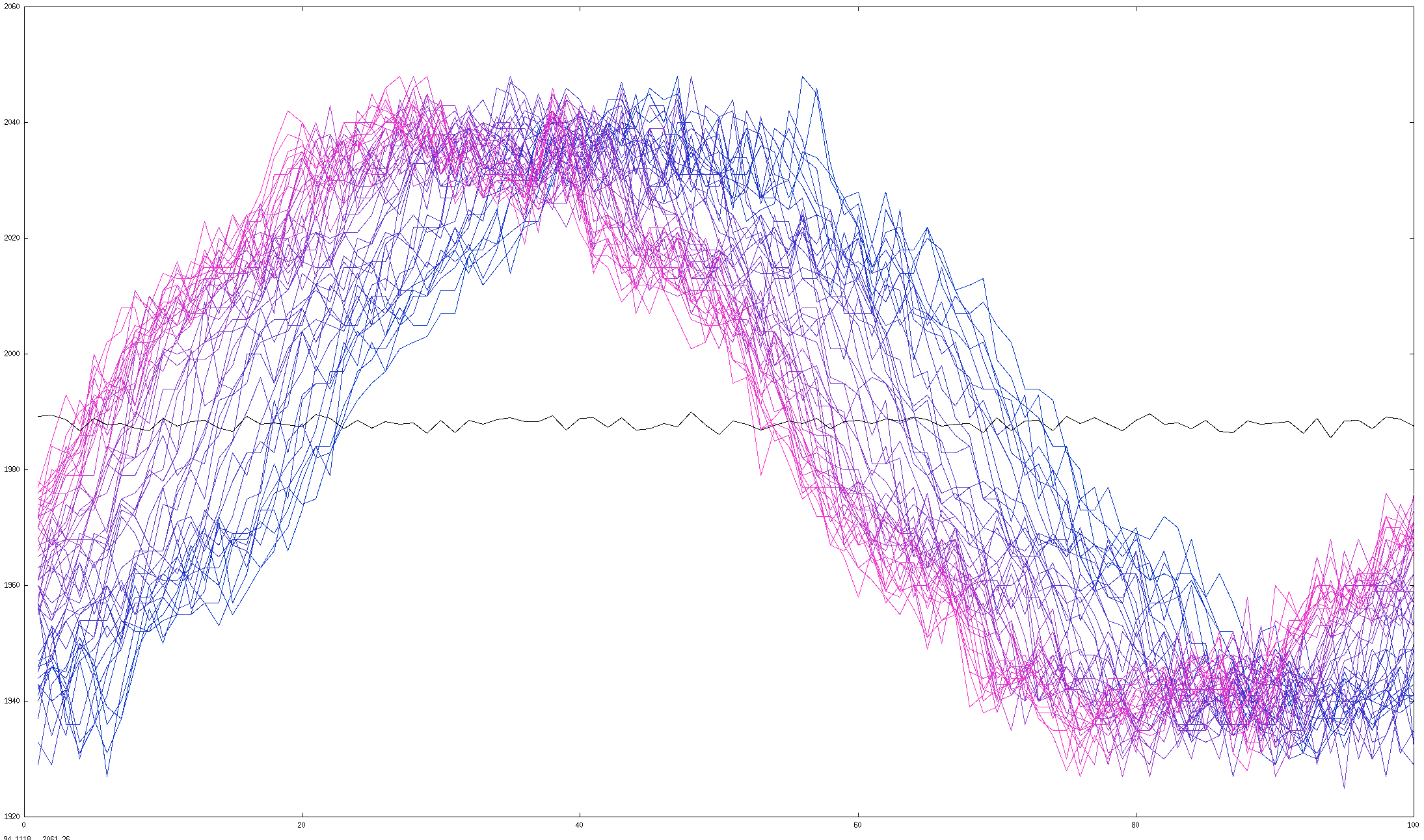
The line is the average current for the 100 buffers. So up to 50 it shows the average of the visualized curves.
Voltage
The voltage curve on the new PCB, in this case with PAN 28 enabed (this means that we do not make use of the direct access to EasyDMA, but use scan mode in software).
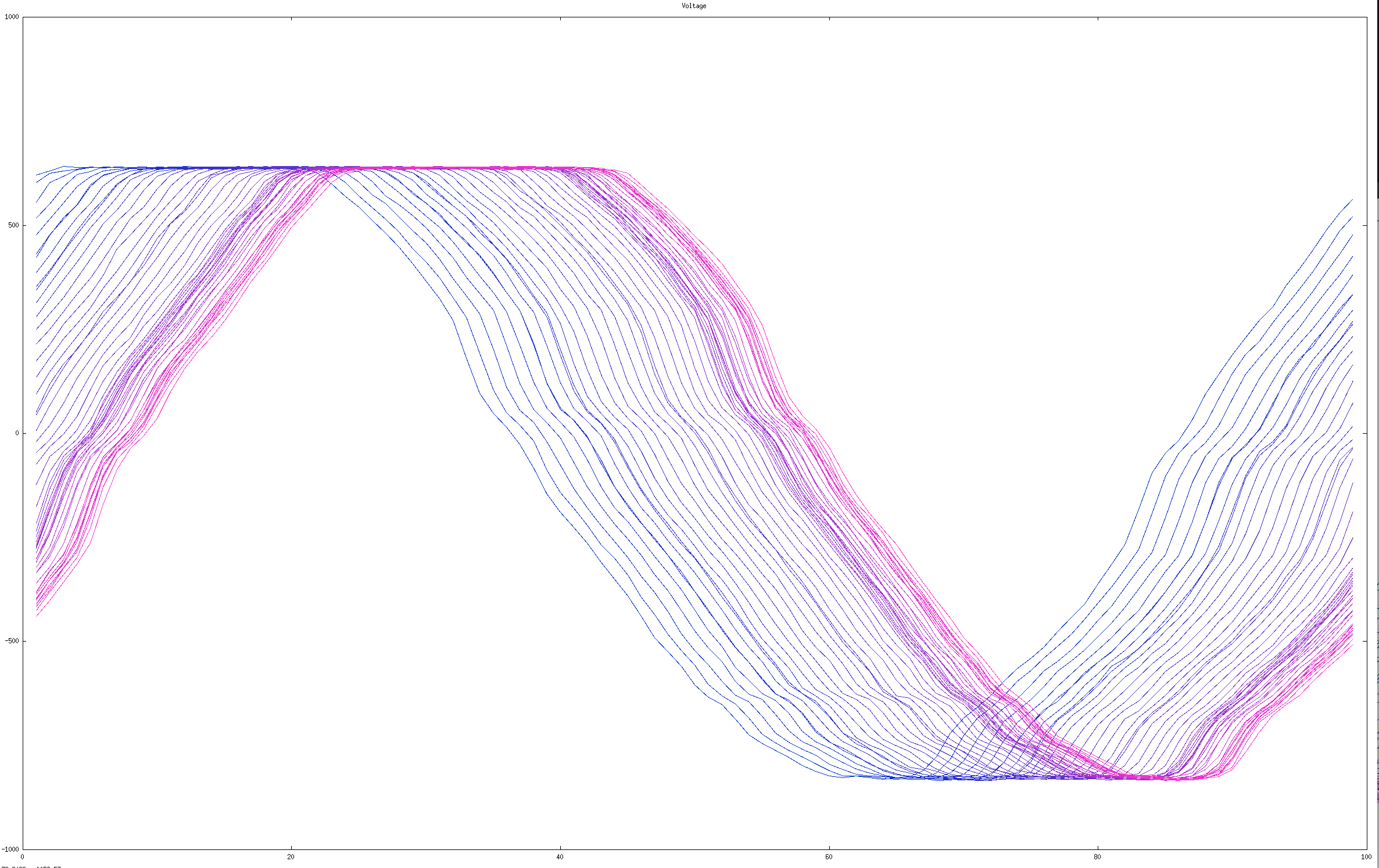
The voltage shifts to the right. If we enable the hardware, the drift becomes more regular.
Note, that the voltage is clipped. This is easily corrected by using the right resistor value.
Drift
A nice visualization of the drift can be seen in the following plot:
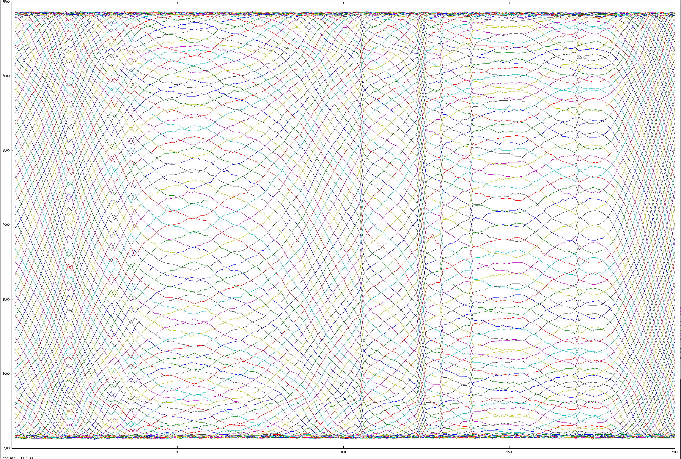
Each curve is plotted vertically (the 100 points in the buffer). Certain points on the curve will move down when the curve is shifted to the right, other points are moving up. Without drift you would expect horizontal lines. With regular drift you would expect a regular periodic behavior. What we see here is that at times the CPU has more things to do than at other times. The drift is changing over time.
Noise
The noise we see currently on the new PCB is less in variance due to the fact that we can use a different scaling factor and use more ADC levels to represent low currents. However, there is noise in the form of downward peaks.
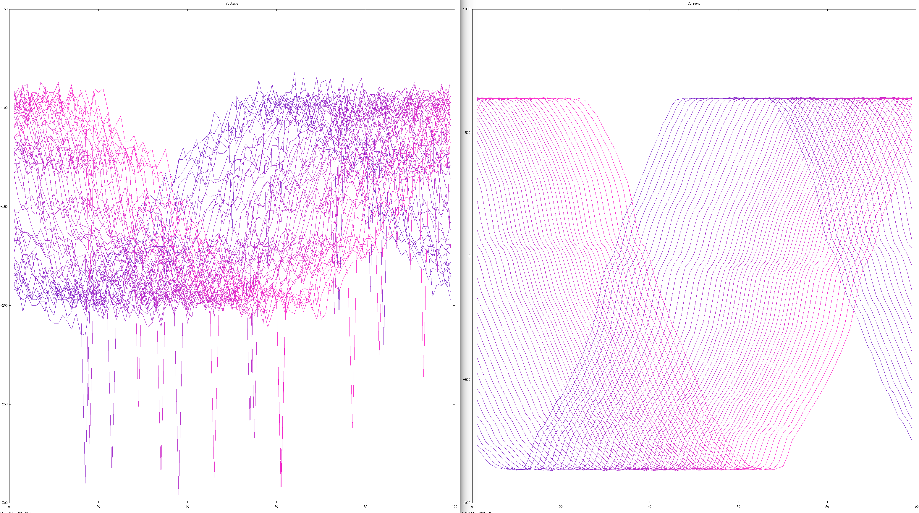
You see that the titles of the images are incorrect. This is due to a channel flip problem. In this case we disabled PAN 28 and use the hardware scan mode of the ADC.
This is a problem noticed about the Nordic hardware by other developers.
- https://devzone.nordicsemi.com/question/97728/saadc-scan-mode-sample-order-is-not-always-consistent/
- https://devzone.nordicsemi.com/question/119588/offset-in-saadc-samples-with-easy-dma-and-ble/
Until now Nordic has not responded with a good explanation. We can reliably introduce a channel flip by using pstorage. A flash erase operation takes about 21 msec. A pstorage_update command uses two flash erase operations under the hood and is able to impact a BLE connection if the connection interval is set lower than 30 msec source. Regretfully, this is not the only way to initiate a channel flip. Also when a BLE discovery process is initiated, the additional amount of work can throw the ADC off.
The priority of the ADC is set to 3. The Softdevice controls levels 0, 1, 4, and 5.
28 July 2017


Show Comments
(not shown automatically to support your privacy)